NOZZLE FLOW WITH VIBRATIONAL NONEQUILIBRIUM
by
John G. Landry
Graduate Student, Old Dominion University, Norfolk, Virginia.
John H. Heinbockel
Professor, Old Dominion University, Norfolk, Virginia.
Willard E. Meador
Senior Scientist, NASA Langley Research Center, Hampton, Virginia.
Abstract
The flow of high temperature nitrogen gas through a
converging-diverging conical test
nozzle is simulated under conditions of thermodynamical
nonequilibrium. The flow is simulated using the Navier-Stokes
equations that have been modified
to include the effects of
intermolecular forces and vibrational nonequilibrium. In
particular, two energy equations
are used. One energy equation accounts for energy effects due to
translational and rotational degrees of freedom. The other
energy equation models
effects due to the vibrational
degree of freedom. These energy equations are coupled using an
improved relaxation time
over the temperature range of the flow. The computational fluid
dynamics algorithm of
Steger-Warming flux vector splitting method was employed to
solve the resulting equations. The equations were also solved
using the implicit
MacCormack method as a check
of the computations. Both of these methods produced consistent
numerical results. Our
simulation showed that a uniform flow was produced outside the
boundary layer and that
nonequilibrium exists in both the converging and diverging
nozzle sections. The boundary
layer exhibited a marked increase in the
translational-rotational temperature. The vibrational
temperature, away from the boundary layer, remains
essentially frozen downstream
of the nozzle and along the center line.
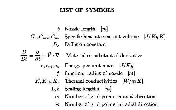
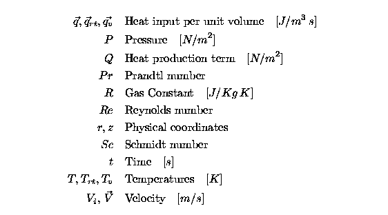
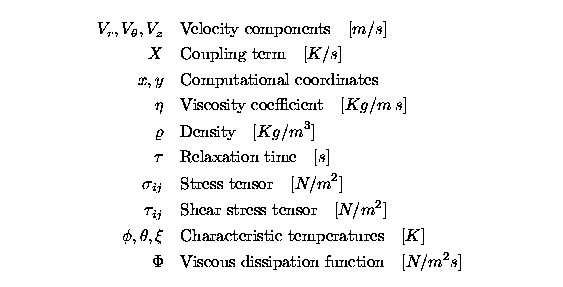
Introduction
Computational fluid dynamics is being used to design hypersonic
wind tunnels and hypersonic vehicles, reference 1. Wind tunnels
are important in aerothermodynamic research and knowledge of
their flow quality is essential. Small conical test nozzles are
also used in various research projects and their flow quality is
also of importance. The research in reference 1 concluded that,
for their nozzle shape, there was poor flow quality in a certain
hypersonic nitrogen flow in a converging-diverging nozzle. The
poor flow was attributed to nonequilibrium effects and expansion
and compression waves crossing the nozzle exit plane. This
raised the question, "What would be the flow quality in a
conical test nozzle under conditions of thermal nonequilibrium?"
In order to answer this question we considered the problem of
flow quality of a high temperature nitrogen gas flowing through
a high expansion converging-diverging conical test nozzle. This
research differs from that of reference 1 in both the shape of
the nozzle, the numerical solution techniques, boundary
conditions and parameter values used in the modeling. This
problem was investigated in the work performed in reference 2
and was motivated by concern of test nozzle behavior
underconditions of thermodynamical nonequilibrium between the
translational-rotational and vibrational
degrees of freedom of the molecules. (This work was supported
under research grant NAG-1-1424.) The modeling of
nonequilibrium effects requires that the Navier Stokes equations
be modified as they do not fully describe energy transfer for
diatomic molecules like nitrogen at high temperatures. We
therefore developed the necessary energy equations describing energy
transfer between a translational-rotational energy mode and a
vibrational energy mode. These energy equations are coupled
using an improved relaxation time associated with this
type of nonequilibrium nozzle flow over the temperature range considered.
NozzleShape
The equations which describe the converging-diverging conical
test nozzle are defined in cylindrical coordinates with the
z-axis representing the center line of the nozzle and
symmetry existing in the theta direction. The nozzle shape is
then described by the radius as a function of z, and is divided
into four sections. Starting at the nozzle entrance the
sections are described by a straight line, a circle, a cubic
spline and another straight line. The location of the points
separating each section are designated a1, a2 and a3. The nozzle
radius in millimeters, is a function of the axial distance in
millimeters, and is given by

Governing Equations of Motion for equilibrium case
For conditions of equilibrium between the degrees of freedom of
a gas one usually solves the Navier-Stokes equations, which
consist of a continuity equation, momentum equations and an
energy equation together with an equation of state, subject to
given boundary and initial conditions. The conservation of mass
is represented by

The conservation of momentum is obtained from the equations
 The coefficient of viscosity is calculated using the Sutherland
formula for nitrogen, references 4,6.
 where the temperature T is in degrees Rankine.
In a single temperature model, equilibrium exists among the
degrees of freedom of the gas and so the change in the total
energy of a fluid in motion is set equal to the changes
in the internal energy, kinetic energy, work done, and heat from
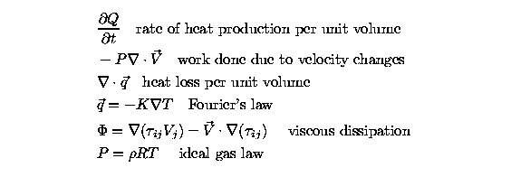
conduction. The internal energy per unit mass, e(T), is a
function of temperature and satisfies

Nonequilibrium considerations
In contrast, under conditions of thermal nonequilibrium, we
assume that initially the gas is such that two temperatures
exist, one temperature representing the translational-rotational
internal energy and another temperature representing the
vibrational internal energy.
When vibrational relaxation occurs, the energy distribution is
changed as the system returns to a state of equilibrium. In
order to model this behavior, the energy generated from the
molecules vibrational degrees of freedom is treated separately
from the energy generated from the translational and rotational
degrees of freedom. We then write the total internal energy as

which represents the sum of the translational-rotational
internal energy and the vibrational internal energy. In
addition, the molecules are assumed to be linear harmonic
oscillators so that the vibrational energy is given by, reference2,

As with the internal energies, the specific heat can be written
as a sum

To obtain an equation for the translational-rotational energy we
utilize the vibrational energy equation (8), and write the
single-temperature energy equation (6) in terms of
translational-rotational and vibrational components to obtain

Subtracting equation (8) from equation (10) yields the translational-
rotational energy equation
 Note that each energy is related to its respective temperature
by a separate specific heat. For fully excited modes, each
degree of freedom contributes RT/2 to the total
energy, reference 4. Each diatomic molecule has three
translational, two rotational, and one
vibrational degree of freedom. Even for low temperatures, the
translational and rotational modes are fully activated, so a
good approximation to the rotational-translational specific heat
at constant volume is 5R/2. The translational-rotational energy
can then be expressed
 where R is the ideal gas constant. The vibrational energy is
found, reference2, to be
 This in turn produces the specific heat at constant volume for
the vibrational mode as
 The heat fluxes are also functions of temperature and are split
into translational-rotational and vibrational components, so that
 The Prandtl number, Pr, is defined as
 The Schmidt number is defined as
 This shows that the vibrational thermal conductivity is a
function of both temperatures, since viscosity is a function of
T and the specific heat is a function of the vibrational
temperature.
For nitrogen, the relaxation time is taken from Meador, Williams
and Miner, reference 3, and is calculated from
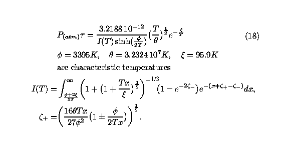
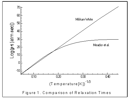
Figure 1 shows the relaxation time derived from equation (18) as
it compares to the relaxation time developed by Millikan-White,
reference7. Note the difference over the low temperature portion
of the graph.
Governing equations for nonequilibrium case
To summarize, in two dimensional axisymmetric coordinates, the
equations which simulate the converging-diverging nozzle flow
fields in the case of thermodynamical nonequilibrium are given
by the following equations
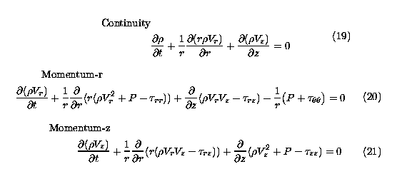
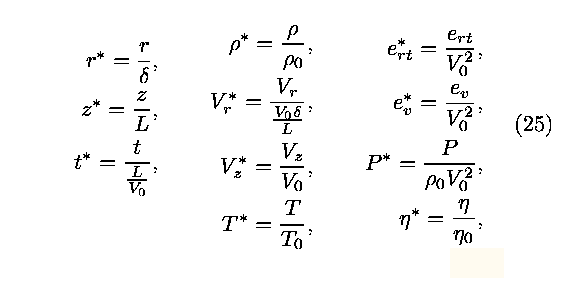
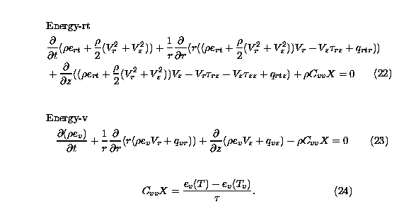 The equations (19) through (24) are scaled by introducing the
dimensionless variables defined by
Finally, the nozzle is mapped to the computational domain by
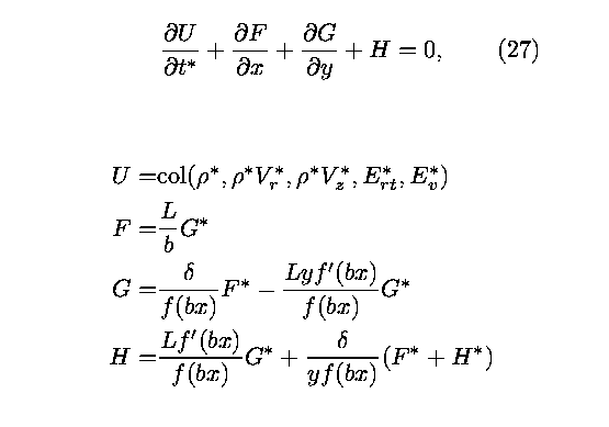
employing the change of variables,

so that the nozzle is mapped to the unit square in the x,y
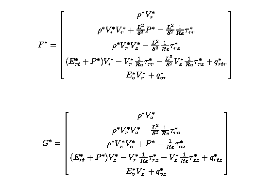
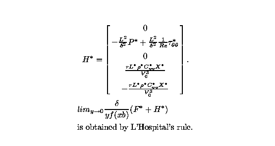
plane. Consequently, the system of equations (19) through (24)
are converted to the weak conservative form
Boundary Conditions
The steady solution of the equations is uniquely defined by the
boundary conditions. In order to obtain a meaningful solution,
boundary conditions must be applied that are not only applied
correctly but are physically meaningful, reference 8. The
boundary conditions are expressed in terms of the primitive
variables and are converted to scaled conservative variables
when implemented numerically.
At the in flow boundary, the translational-rotational
temperature is held fixed at some initial value. The vibrational
temperature is assumed to be in equilibrium with the
translational-rotational temperature at the inflow boundary and
is also held constant at the inlet. In the computational
coordinates, the gas is assumed to enter the nozzle parallel to
the centerline, so the radial velocity is assumed to be zero.
The axial velocity is held fixed at an initial velocity.
Finally, to simulate subsonic inflow and supersonic outflow
conditions, an analysis of the flow characteristics of Euler's
equations suggests that one boundary condition must be left free
to change with the solution of the interior flow, references
9,10. To this end, the density values are extrapolated from
interior data. In the computational domain, this represents the
condition that the partial derivative of the density with
respect to distance is equated to zero. This is equivalent to
the conditions

in the solution domain.
For supersonic flow, at the far-field boundary, all variables
are extrapolated. From the relation

the pressure is also extrapolated.
The symmetry of the nozzle is used to specify the conditions on
the center line. Assuming that the quantities above the center
axis are mirrored by those below, the partial derivatives of the
primative variables in the radial direction are equated to zero.
Also along the center line we set the radial velocity to zero.
Lastly, boundary conditions on the nozzle wall are governed by
the nozzle shape and the viscosity. On the nozzle surface we
assume a no-slip boundary condition so that the radial and axial
velocities are set equal to zero at the wall. Questions arose as
to the correct translational-rotational and the vibrational
temperatures at the nozzle boundary and so two scenerios are
considered. The first case assumed that since the gas is not
moving at the wall it is assumed to be in equilibrium. Thus, we
used the boundary condition that

The second case considered both the translational-rotational and
vibrationaltemperatures to be extrapolated at the wall. This
produced the boundary conditions

Following the recommendations given in reference 15, the
pressure gradient normal to the wall is set equal to zero. The
density on the boundary is then calculated using the ideal gas
law evaluated on the boundary.
Initial Conditions
The choice of initial conditions is also important. Values that
are too far from the steady solution can make the numerical
solution unstable. Also, the closer the initial conditions are
to the steady solution, the less time is required for
convergence. To minimize the convergence time, we approximate
the steady state solution with the steady solution of the
corresponding one-dimensional inviscid problem. The flow is
assumed to be in thermal equilibrium and isentropic. The
one-dimensional values are then extrapolated and smoothed to
match the boundary conditions. Further, in the computational
coordinates the radial component of the input velocity was set
equal to zero. For low pressure nitrogen gas flow a stagnation
prssure of 50 psi and stagnation temperature of 3000K defined
our simulation input parameters.
Numerical Methods and Results
The system of nonlinear partial differential equations given by
equation (27) are discretized over a nonuniform grid which
consists of n+1 rows and m+1 columns. We let

denote the solution at an interior grid point. The points in
rows 0 and n or columns 0 and m are boundary points and are
updated after each iteration. In the axial direction the grid is
divided into four regions and in the radial direction it is
divided into three regions. This forms twelve separately spaced
regions, where the number of grid points in any region can be
adjusted. The spacing between rows and columns varies to allow
for a finer resolution near the throat and in the boundary
layer. In general, the irregular grid spacing goes from fine to
course in the axial direction and from course to fine in the
radial direction.
The system of equations (27) was solved using the implicit
method of Steger-Warming flux vector splitting described in
reference 11. As a check on the results, the steady solution
was also computed using the implicit MacCormack method described
in reference 12. Both techniques used a 81 by 41 grid and gave
consistent results. Details of the implementation of these
methods are provided in reference 2.
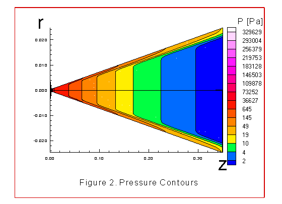
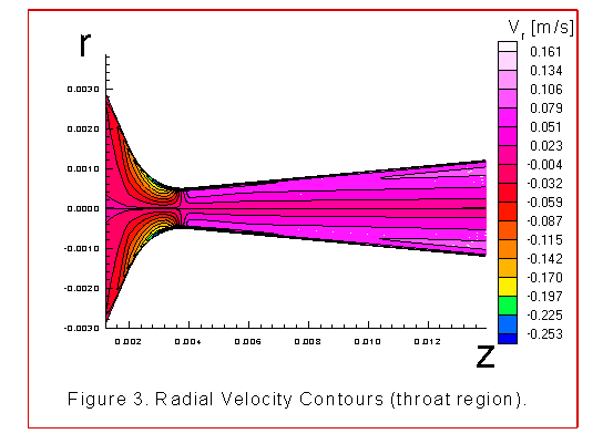
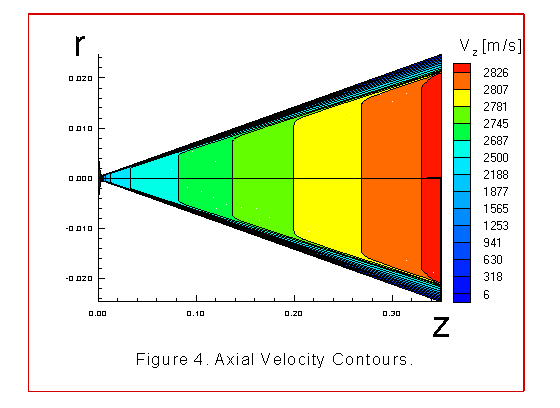
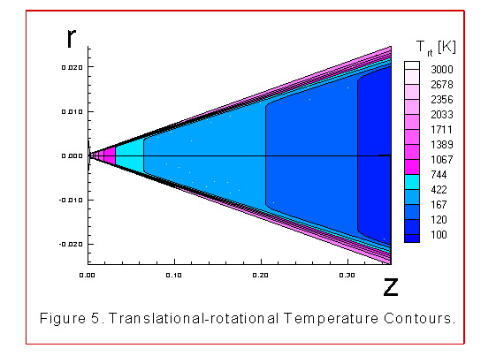
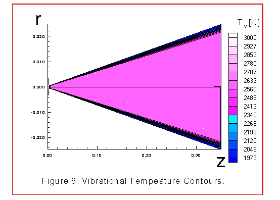
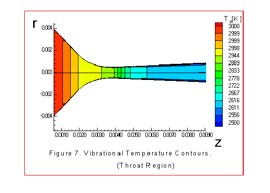
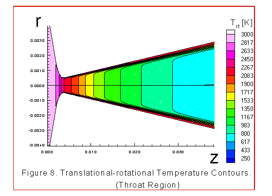
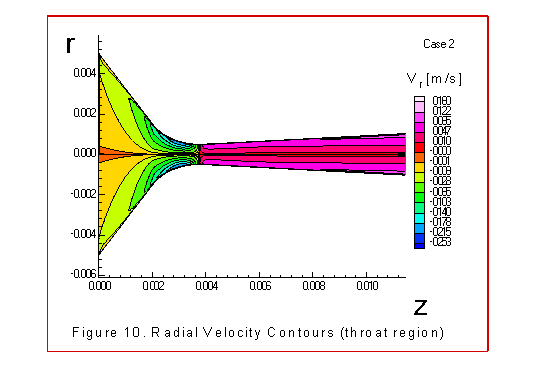
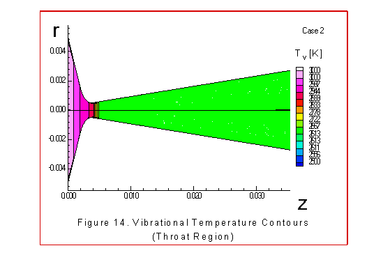
The figures 2 through 8 illustrate various contour plots of the
numerical results describing the flow for case1, where the
translational-rotational temperature was equated to the
vibrational temperature at the wall. These figures give the
pressure contours,radial velocity contours, axial velocity
contours, translational-rotational temperature contours and
vibrational temperature contours.
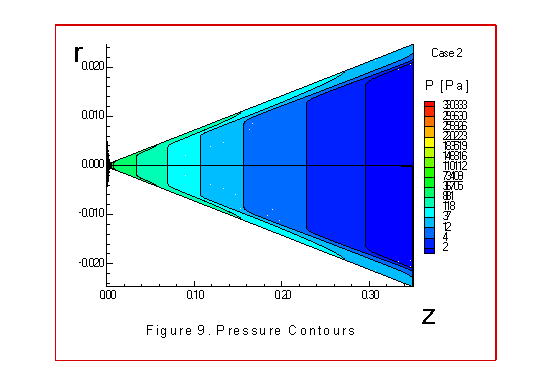
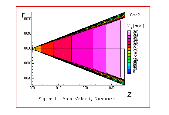
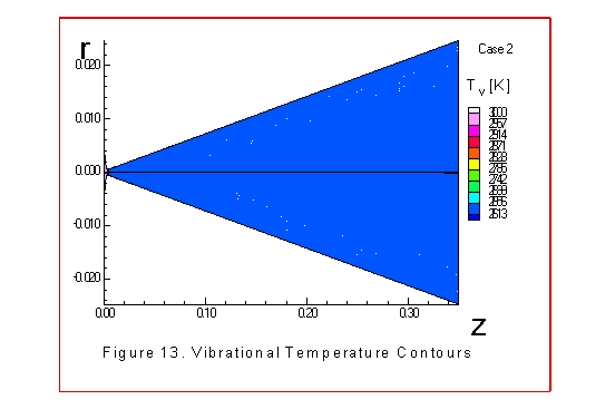
The figures 9 through 15 illustrate similar contours
for the case 2, where both the translational-rotational
temperature and vibrational temperature were extrapolated at the
the wall boundary. We make the following observations concerning
these graphs. Note that the pressure drop is large to insure
that a shock wave does not occur between the throat and exit
plane. The radial velocity contours match intuitive
expectations. Usually these contours are not plotted as their
values are several orders of magnitude less than the axial
velocities. In both cases 1 and 2 the axial velocity contours
increased from 6m/s to 2837m/s at the exit plane with uniform,
almost linear contours in the diverging section of the nozzle.
The size of the boundary layer is small as is expected.
There is a big difference in the temperature contours. The
translational-rotational energy experiences a large loss of
energy as the gas expands through the throat. This temperature
changes from 3000K at the entrance to 112K at the exit. These
changes, along with the large pressure drop, suggested that
maybe the continuum model was breaking down. A
check on the Knudsen number showed that we were still within the
range of a continuum model, reference5.
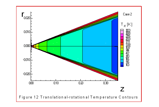
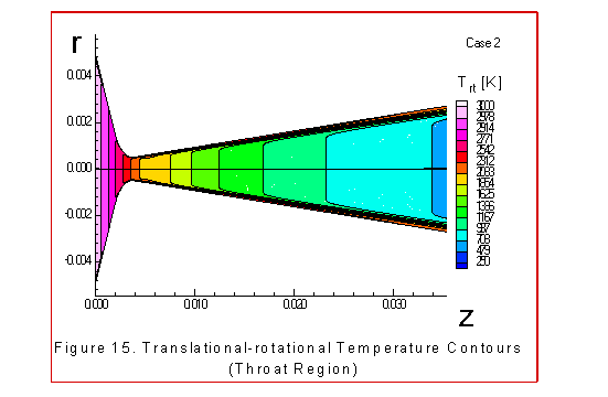
Boundary behavior is noticeable in figures 4, 5 and 6. Note that the
rotational-translational temperature is increasing toward the
wall. This can be explained by the energy equation (22) where
for values of zero wall velocities we find

Observe that when the rotational-translational temperature is
less than the vibrational temperature, then the difference in
the last term of equation (33) is negative and so the coupling
term increases the internal energy and therefore there is an
increase in the translational-rotational temperature. Also as
the gas nears the wall it slows and there is more time to relax
with an increase in the vibrational to translational-rotational
energy transfer. The most noticeable feature of the vibrational
temperature contours is the freezing of the vibrational
temperature, along the centerline, downstream of the throat.
This is consistent with what other investigators have observed
for their models, references 1, 13, 14. However, the2 flow is
not in equilibrium before the throat,as suggested in reference
13, because the translational-rotational temperature drops much
faster than the vibrational temperature in the converging
section as illustrated in the figures 7 and 8.
In the diverging portion of the nozzle the vibrational
temperature freezes while the translational-rotational
temperature steadily decreases. Near the wall boundary and far
down stream the translational-rotational temperature is
increasing faster than the vibrational temperature is decreasing.
This type of behavior may be one type of a driving force leading
to turbulent motion. This can be seen in the radial velocity
contours illustrated in figure 3.
In comparing the results from cases 1 and 2 we find that
requiring equilibrium of temperatures at the wall produced some
turbulent behavior which begins after the nozzle
throat within the boundary layer region. Down stream of the
throat the effect is less noticable. In addition, there were
larger pressures at the inlet and wall boundary due to
the extrapolated temperature boundary conditions.
Concluding Remarks
Other investigators have included vibrational nonequilibrium in
their models of nozzle flow, references 1, 13, 14. Our modeling
of vibrational nonequilibrium is consistent with that of the
previous researchers with differences in boundary conditions,
relaxation times and use of mach number. By comparison with
other research,we have used an improved relaxation time over the
temperature ranges considered. Our results indicate that the
flow quality was good. We did not obtain the poor flow quality
as found in reference 1, mainly because our nozzle shape was
conical and was different than that of reference 1. Our
numerical calculations were different also. The reference 1
states that they used the speed of sound and mach number
extensively in their CFD algorithm. In our work we have not
used the speed of sound or mach numbers anywhere in our
calculations since mach numberis calculated from sound speed
which is a function of sound frequency in nonequilibrium gas
dynamics. This sound frequency is unknown so any use of mach
number or sound speed could be misleading. Both of the numerical
methods of Steger-Warming flux vector splitting and the implicit
MacCormack method were used to check the validity of our
numerical results. Both of these methods proved capable of
handling the complexities of our modeling and gave consistent
numerical results.
REFERENCES
- Canupp P., Candler G., Perkins J., Erikson W., "Analysis of Hypersonic Nozzles
Including Vibrational Nonequilibrium and Intermolecular Force Effects", 30th Aerospace
Sciences Meeting, AIAA92-0330, January 1992.
- Landry J. G., Nozzle Flow with Vibrational Nonequilibrium, Ph.D. Thesis, Old
Dominion University, December 1995.
- Meador W. E., Williams M D., Miner G. A., "Scaling of Vibrational Relaxation in
Nitrogen Gases", (NASA Technical Report, in preparation).
- Kauzmann W., Kinetic Theory of Gases, W. A. Benjamin, Inc., 1966.
- Hirschfield J. O., Curtis C. F., Bird R. B., Molecular Theory of Gases and Solids,
John Wiley and Sons, 1954.
- Benedict R.P., Fundamentals of Gas Dynamics, John Wiley and Sons, Inc., 1983.
- Millikan R.C., White D.R., "Systematics of Vibrational
Relaxation", Journal of Chemical Physics, Vol. 39, No. 12,
3209-3213, December 1963.
- Shang, J.S., "An Assessment of Numerical Solutions of the Compressible
Navier-Stokes Equations", AIAA 17th Fluid Dynamics, Plasma
Dynamics and Lasers Conference, AIAA 84-1549, June 1984.
- Hoffman K.A., Chang S.T., Computational Fluid Dynamics for
Engineers, Vol1. and Vol.2, Engineering Education System,
Wichita, Kansas, 1993.
- Thomas P.D., "Boundary Conditions for Implicit Solutions to
the Compressible Navier-Stokes Equations in Finite Computational
Domains", AIAA Computational Fluid Dynamics Conference, AIAA
79-1447, July, 1979, Williamsburg, Va.
- Steger J.L., Warming R.F., "Flux Vector Splitting of the
Inviscid Gasdynamic Equations with Applications to
Finite-Difference Methods", Journal of Computational Physics 40,
263-293, 1981.
- Anderson D.A., Tannehill J.C., Pletcher R.H., Computational
Fluid Mechanics and Heat Transfer, Hemisphere Publishing Co., 1984.
- Gnoffo P.A., "Application of Program Laura to Thermochemical
nonequilibrium Flow through a nozzle", Hypersonic Flows for
Reentry Problems, Vol.2, Springer-Verlag, 1145-1158, 1991.
- GokÇen T ., "Computation of Nonequilibrium Viscous
Flows in Arc-Jet Wind Tunnel Nozzles", 32nd Aerospace Sciences
Meeting, AIAA-94-0254, Jan., 1994.
- Yee H.C., Warming R.F., and Harten A., "Implicit total
variation diminishing (TVD) schemes for steady state
calculations, "J. Comput. Phys., 49, 377-393, 1983.
Go back to the Faculty and Staff listing


